From The Rail Engineer (April 2014):

So what is acoustic sensing?
Since fibre optic cables are now commonplace alongside railway tracks and roads, it may not be necessary to lay a dedicated cable but merely allocate a spare fibre in an existing cable. The positioning of the fibre relative to the likely interference source is not critical but there are optimum places where it will perform best.
For a railway line, burial about 10cm down near to the sleeper end will enable detection of even the smallest incursion on to the track while having two fibres, one each side of the track, is perfection. Unless a dedicated cable is to be laid, however, these situations will not be the norm. An existing cable laid in a concrete trough, a buried pipe, or directly in the ground, will still pick up acoustic energy from close by events.
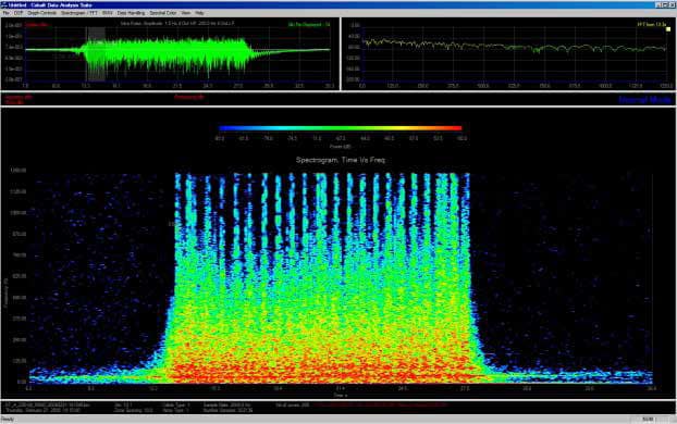
Clearly, a passing train will give a very strong signal and any rock fall will equally give a clear indication of something happening. A track gang working with shovels to dig holes or pack ballast will be picked up, as will someone using a hacksaw to cut cables in the route. With experience, every type of occurrence creates its own recognisable pattern which can then be ‘decoded’ at the monitoring point.

System Development
Having established the technical principle, turning this into a practical way of realizing the potential is a project in itself. OptaSense, a company within the QinetiQ group, started business in 2008 with just a handful of employees. It has now grown to over 160 people. QinetiQ brought together decades of sonar signal processing expertise and capability from the QinetiQ group with a new fibre optic distributed acoustic sensing technique from an external company called Sensoptics. The combined capability became OptaSense and is now the world’s Acoustic sensing CLIVE KESSELL the future for rail monitoring? The leading distributed optical sensing company with research, development and manufacturing based in the UK and the majority of its products exported around the world.
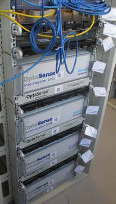
The OptaSense DAS system injects a 1550 nanometre wavelength pulse of light into the fibre 2,500 times a second. The fibre length operated by a single device is typically 40 km and is a single-ended system.
DAS works on the principle that no fibre is perfect and throughout the length of the cable, there will be minor perturbations that cause small reflections of light that in the quiescent state show up as tiny peaks on a computer screen at the measuring end. The unique pattern of these peaks allows the fibre to be graduated into sample points. These can vary between every 1- 15 metres, although typically the measurement section is 10 metres. Over a 40km length, some 4000 measurements of the fibre can be interpreted which pinpoint any event along the cable with considerable accuracy.
OptaSense®
Reducing the cost of asset ownership
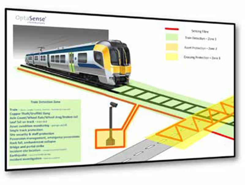
Through a single system our Distributed Acoustic Sensing technology creates up to 4,000 virtual microphones along any 40km length of standard fibre optic cable – enabling permanent monitoring of rail track, rail assets, personnel and health and safety hazards.
Our real-time, detect-classify-locate-alert technology enables immediate response to hazards, threats, disturbance and activity along potentially thousands of kilometres of track through one easy to deploy solution.
A single OptaSense® system now delivers the functional capability of several discrete sensors, delivering operational performance & safety whilst minimising trackside infrastructure.
We are building Earth’s Nervous System™
Practical Realisation
So far, so good – but interpreting events needs to be taken a step further. Along a 40km length some events will happen on a very regular basis; road vehicles passing over or under the track on a bridge, a level crossing for either road or foot users, an access walkway alongside the track, and such like.
To prevent alarms being raised every time a routine event happens, the alarm for that 10 metre zone can be disabled and it would be the customer’s choice as to whether every occurrence was recorded.
Another differentiator will be the type of acoustic energy detected and the pattern recognition that this generates. Thus someone digging a hole will be seen as different to someone using a hacksaw. The customer might choose to alarm for one but not the other, based on their threat profile.
Being able to present events in a manner that can be easily interpreted at the control point is a crucial element of the system. With so much data being collected and stored, it would be tempting to over-provide information to the controller, thus causing bewilderment and confusion as to what is exactly taking place. OptaSense has therefore put considerable effort into making the monitoring screen user friendly and providing operators with Decision Ready Data™.
A variety of data options is available, and the choice will depend on the type of control point being used. In a Traffic Management or Rail Control Centre, where the operations staff have other duties to perform, it might just be a simple alarm that triggers an interrogation by a member of the technical support staff. In other implementations, the system is integrated into the process control systems directly and activates prescribed actions e.g. changing signals or sending a preset message. What is important is that an event can be accurately detected, classified and located in real time. This information is presented in a decision-ready format to allow the appropriate response, for example the dispatch of a team to investigate onsite or a police call out.
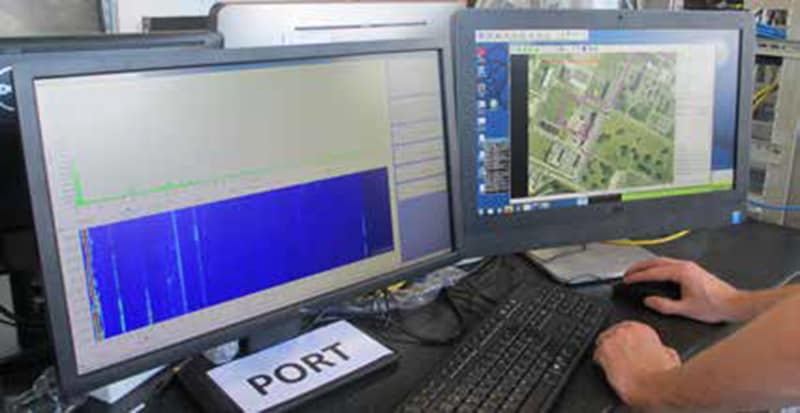
To demonstrate the capability, OptaSense has run out a 3km length of buried fibre optic cable around its Winfrith facility, part of which is runs alongside the Poole to Weymouth rail line just to the west of Wool Station. This cable is linked to a typical monitoring station setup complete with CCTV.
In a demonstration of the remote monitoring capability, two-way radio was used to instruct a person outside to perform a number of threat scenarios such as cable theft. The results were all immediately visible in the monitoring station..
The proximity of the site to the southern boundary of the Poole – Weymouth rail line means the passage and health of trains passing along this line can be monitored. OptaSense believes it would be perfectly possible to link the system into a spare fibre of the FTN cable and thus monitor events on the line over a 40km distance.
DAS technology could replace a number of conventional trackside sensors thereby reducing the cost associated with track monitoring. Under the collaboration, a total of 25 different test scenarios are being investigated including SIL4 applications (safety integrity level 4 – the most dependable level of European Functional Safety Standards).

Future Potential
Customers who have experience of the OptaSense systems are enthusiastic about potential uses beyond the current ones of train or vehicle movement, rock fall, cable theft, wheel flats and presence of people. There are aspirations to move up the SIL ladder with perceived applications being:
- Hot axle box detection by noticing a different sound of one axle compared to others;
- Train integrity by continually counting axles as the train progresses;
- Monitoring the operation of point machines or level crossing barrier motors by detecting changes in machinery noise to detect potential failure;
- Improving user-worked crossing safety by giving time before the train arrives;
- Train positioning information as a feed into signaling systems

All long linear asset industries know the trade-off between the desire to monitor the whole length of an asset (rail, road, pipeline and border) and the prohibitive cost that this would entail using conventional technology. OptaSense has a vision to build the Earth’s Nervous System™ where these assets – the arteries of global commerce – are protected and managed. This vision appears to be both achievable and affordable.

